7.0 VISUAL – SketchUp Integration
Contents
7.0 VISUAL
– SketchUp Integration
7.1.1 SketchUp
Integration - Main interface
7.2.1.8 Transmission Lines Creator
7.2.1.12 Coordinate system setup/exporter
7.2.1.20 Obstacle Object Creator
7.3.1.1 Use the 3D warehouse to bring items
into windPRO photomontage
7.3.1.2 Create/edit elevation data and
import in windPRO
7.4.1.2 Creating animation in SketchUp
7.4.1.3 Exporting to Google Earth
7.1 Introduction
The SketchUp Integration tool makes it possible to export elements from windPRO to SketchUp and from SketchUp to windPRO. Making the bridge between these two powerful softwares gives access to benefit from the strength of each one. Both SketchUp and/or windPRO users will find advantages in the Integration tool, for example:
· Create a SketchUp project with any of the many background maps, elevation sources supported by windPRO worldwide, and work in a real-world GIS coordinate system
· Add vegetation and/or fences around the PV or wind farm areas in Photomontage
· Visualize power transmission masts and lines in a photomontage with a great level of details and accuracy
· Use the huge SketchUp 3D warehouse and bring models back into windPRO to get these visualized in Photomontage.
· Visualize Photomontages directly in SketchUp, with very high accuracy compared with existing SketchUp tools
· Visualize shadows correctly from rotating WTG’s or from PV panels
· Edit Solar PV layouts directly in 3D
· Export Solar PV models to Google Earth
· Show and edit a windPRO project in 3D, show result layers as 3D volumes and get access to the world of VR and AR.
Open the tool using this button:
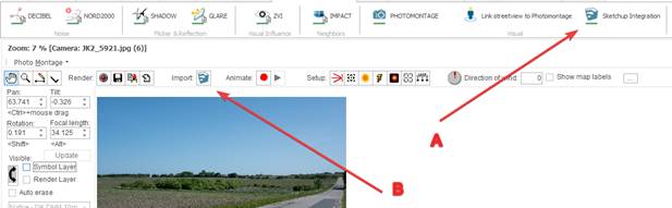
A. This opens a session with SketshUp with a set of Creators.
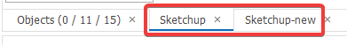
B. This also opens a session with SketchUp, but this session is associated with the present Photomontage. This is an advantage if working with the Mask creator, where the masks is only relevant for a specific camera, and not wanting to clutter the main SketchUp project created with option A.
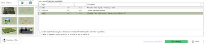
The main window in the SketchUp Integration Tool looks like this:
The Help and Information
tab contains helpful links an resourses about using the tool. This is focused
by default when the tool is first opened:
![]()
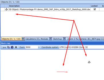
The focus buttons
can be used to switch to the Photomontage window, or to SketchUp.
![]()
The SketchUp icon is animated when SketchUp is processing a task created from windPRO.
With the SketchUp integration tool, the workflow consists in creating “Creators” which then will have to be run. A creator is an element that creates elements in SketchUp/windPRO such as:
· Terrain surface
· WTGs, Solar PV areas
· Photomontages
· Camera points
· Vegetation, Fence, transmission lines
· Buildings
· Masks
· Shape files, DWG, dxf files
· 3D objects
· Text objects, Line objects, Obstacles
· Coordinates system information
· Result layers, Resource maps, CFD maps
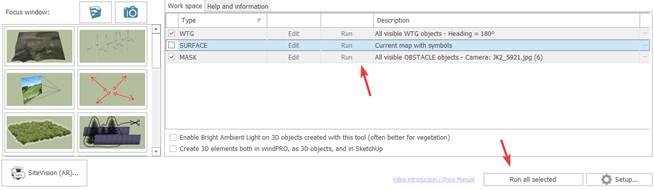
In the main interface, each line corresponds to a creator. The same creator can be run multiple times, alone or together with other Creators. It can also be edited and deleted.
Before running a creator, SketchUp must be loaded by windPRO:
![]()
If SketchUp is not installed or found by windPRO, go to the next chapter, and read how to set it up.
When SketchUp is loaded, the following message (can be disabled) should appear.

It is then possible to run the creators by using the individual “run” button or the Export all selected items button at the bottom:
From the main interface it is also possible to re-import automatically to windPRO (See 7.3.5).
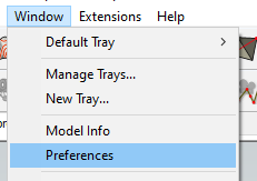
Pressing the Setup… button in the main interface opens the SketchUp Setup dialog.
7.1.2.1 General setup
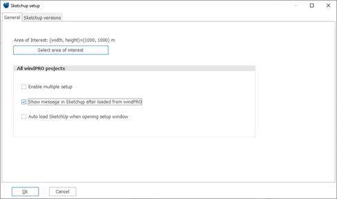
Area of interest: It is possible to define an area on the map, that can later be used from the individual setups. This can be useful if wanting to export the exact same area from different setups.
Enable multiple setup: Check the option to have more than one setup window open in each windPRO project. Each setup window will then be connected to its own SketchUp project.
Show message in SketchUp after loaded from windPRO: This defines if this message should be shown when SketchUp is loaded from windPRO
Auto load SketchUp when opening setup window: With this option, windPRO will automatically click the Load SketchUp button when the setup window is opened.
![]()
7.1.2.2 SketchUp version
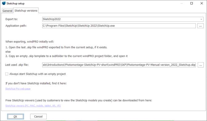
Export to: To select which version of SketchUp to use. windPRO has preselected the expected paths to the SketchUp.exe files, but if they are installed in different folders, it must be set manually.
Application path: If SketchUp is not installed in the default installation folders, then it must be selected here where it is located.
Last used .skp file: To define the SketchUp project associated with this setup. If it is blank, as it is first time, then windPRO will copy a template project to a subfolder to the current windPRO project and use this file. It can be changed manually to a different filename. If a SketchUp project has been loaded by windPRO and then saved to a different name, then windPRO will use this new name.
Always start SketchUp with an empty project: Check this to bypass the Last used .skp file and start with an empty project.
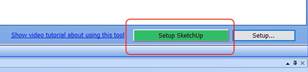
7.1.3 SketchUp installation
If SketchUp is installed and the button Load SketchUp is displayed, then you can skip this chapter.
![]()
If SketchUp is not installed, or if windPRO cannot find the SketchUp installation, a setup must be performed.
Click the “Setup Sketchup” button:
Click here to go to the SketchUp download page:
![]()
If you do not have a SketchUp subscription, you need to sign up or get a trial version:

If you already have one, then you can download SketchUp here:
https://www.sketchup.com/download/all
After installing SketchUp this button appears. Click it to start SketchUp.
![]()
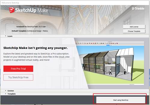
If SketchUp Make 2017 is used, then click the below button “Start using SketchUp” to get started:
7.2 Creators
In the following sections, each type of Creator is explained.
Common features for all types of Creators:
1) Description: the description text is shown in the list of created creators and also used as Layer name in SketchUp. When the description is not used as a Layer, it will be specified.
2) When Creators are related to objects, they can be selected in three possible ways:
· All objects from visible layers
· All objects in the project
·
All selected objects (just
before clicking Run)
3) Which object are exported to SketchUp is not determined by when the creator is edited, but rather when the creator is run.
To
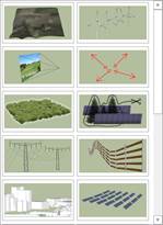
create a new creator, simply click an item in the left list:
7.2.1.1 Surface Creator
This creator can export an elevated windPRO background map to SketchUp.
Export an elevated windPRO background map to SketchUp.
There will always be used a maximum 10.000 points to create the surface map. This means the resolution in meters depends on the size of the exported area.
Any of the maps used in windPRO can be used. This gives access to a wide range of maps for the whole world including Open Street Map, user defined WMS/TMS maps, scanned maps, screenshots, world files and overlays from Google Earth.
Link to windPRO help about background maps
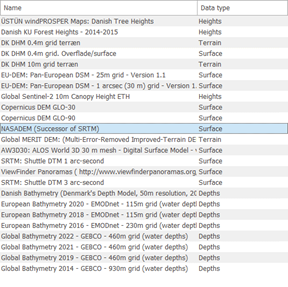
The map creator uses the default elevation model from the windPRO project. windPRO has access to a wide range of global and local maps. The list of available elevation data sources depends on the project location:
Also, elevation data can be loaded from many file formats, including Surfer Grid, GeoTiff, xyz and Shape format.
Link to windPRO help about grid elevation data (recommended)
Link to windPRO help about line elevation data
Creator setup:
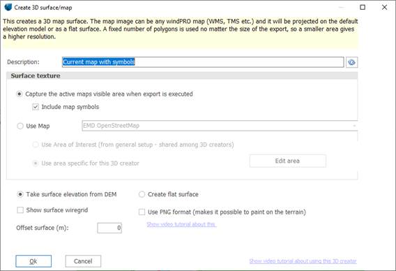
Capture the active maps visible area when export is executed: Use this option to export the part of the map that is visible at the time the creator is run.
Include map symbols: Select if the map symbols should be rendered on the exported map too. This way result-layers can be exported to SketchUp in a simple way.
Use Map: Use this option to select a fixed map and area for the surface export. The map can be selected from the drop down dialog. This would produce a higher quality map.
Use
Area of Interest (from general setup): If this
is selected, then the area to export is taken from the general setup that is
shared with other creators.
Area specific to this creator: to export an area that is specific to this creator.
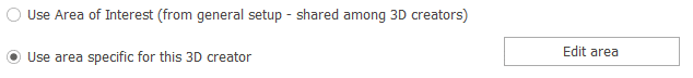
Press “Edit area” to define the selected area.
Create
flat surface: Use this option to create a flat
map, and not use the elevation model. This can be useful when drawing new 3D
objects on the surface where it is a lot easier when the surface is flat.
Objects created on a flat surface can later be moved vertically to the correct
vertical position.
Also it can be useful when exporting result layers.
Show surface wire grid: Check this to let the lines in the surface be visible in SketchUp. This can also be edited inside SketchUp after the export.
Offset
surface: If surface level is taken from DEM, then
this value is added to the DEM. If exporting a flat surface
then it will use this level.
2.1.1.1 Paint on the terrain.
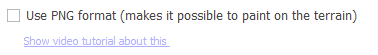
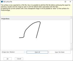
When selecting this option, it is the terrain file is created in .png format, instead of the more efficient .jpg format. The advantage is that PNG supports transparency. When this is selected the user is given an opportunity to edit the surface during the creation of the 3D surface:
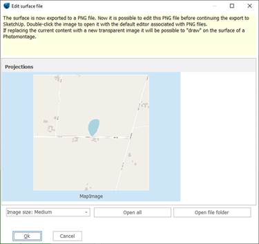
In this dialog the image can be loaded in the editor associated with PNG, and modified before continuing.
Example using Photoshop:
1.
Create a new layer on top of
the map image:
2.
Paint desired content on the
new layer:
3.
Delete the background map
image:
4.
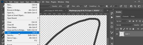
Press the save button:
5.
Press the OK button in windPRO:
6.
Show it together with a
Photomontage image in SketchUp:
7.
If wanting to use this as a
background image in Photomontage, the image can be exported and saved as a jpg,
and used as background image in Photomontage instead of the original photo, or
the surface layer can be exported to windPRO and rendered as a 3D object:
 or
or
7.2.1.2 WTG Creator
Use the WTG creator to export WTGs from the project to SketchUp.
In the setup it can be selected which direction the WTGs should face, and which WTGs to export.
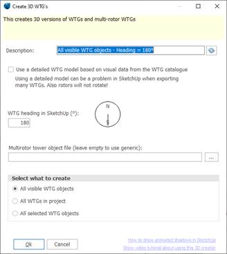
It is at the time the creator is run that it is determined which WTGs to export, not when the creator is edited.
The size of the WTGs is picked up from the WTG object properties (hub-height and rotor diameter), but the model itself is generic, and the same one used for all WTG types. To visualize WTGs with the correct visual properties, use windPRO PHOTOMONTAGE module.
Select this option to use detailed visual 3D properties.
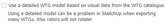
Do not use this option if creating a huge number of WTGs as it may bring down SketchUp. Also, the detailed WTG’s cannot rotate in SketchUp.
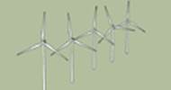
This option is used if creating multirotor WTG’s:
![]()
Multirotor WTG’s does not have the visual properties in the WTG catalogue for the tower construction, and a dae file must be selected for this purpose. If nothing is selected, a default tower is generated.
Make the WTG rotate
To make the WTG rotors rotate in SketchUp, select this option in the Tools menu:
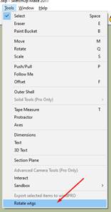
This can be quite resource intense for the computer, so do not activate rotation while editing the SketchUp model. Strange things may happen.
Rotating WTGs only work when SketchUp is started from windPRO.
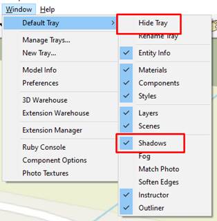
Show WTG shadows
The Video tutorial link also demonstrates how to show shadows of WTGs in SketchUp.
Make sure the default tray is not hidden, and the Shadows toolbar is turned on:
Then this setup should appear in the user interface:
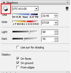
Turn shadows on by pressing the button in the upper left side. Then the sliders can be used to adjust the light.
If showing shadows is not visualized smooth and the computer has problems keeping up the speed, then it can be changed what elements that should cast and receive shadows. Select an element (make sure it is unlocked) and change the shadow settings:
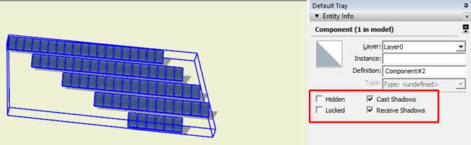
Switching off irrelevant elements often has a great influence on performance.
7.2.1.3 PHOTOMONTAGE Creator
With the PHOTOMONTAGE Creator photo-matching can be performed with unseen precision in SketchUp. PHOTOMONTAGE is a tool created for rendering 3D models correctly on a photo, primarily WTGs and Solar PV areas in windPRO, and it has a long list of tools available for calibrating the camera model. When the camera is calibrated correctly the photo and/or the camera viewpoint can be exported to SketchUp, and objects in the SketchUp project can be visualized on the photo with great precision.
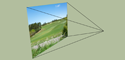
After exporting a PHOTOMONTAGE image to SketchUp it is placed floating in the 3d space and it is put on its own layer. A new Scene is created. When this scene is selected, the camera is moved to the correct position to view the photo correctly.
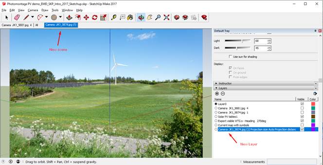
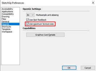
The SketchUp preference should be set to use “Maximum texture size” to get the best quality.
Exporter setup:
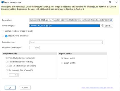
Camera object: the wanted camera
object is selected. Before using a camera object, it must be calibrated in the PHOTOMONTAGE
module. The object description is used as Scene name in SketchUp.
Projection type: perspective projection is used with a normal photo, or cylindrical with a Panorama.
Projection distance: indicates the distance from the camera position to the image position in SketchUp. Normally the distance should be large enough to put the image “behind” any other objects in the model. It should not be extremely large or small. If it is very small then the precision of the visualization can suffer.
Projection size: Normally it is preferable to use a zoom that makes the image fill out the screen, but still not being truncated (auto). Often this would lead to blank spaces at either the sides or the top/bottom:
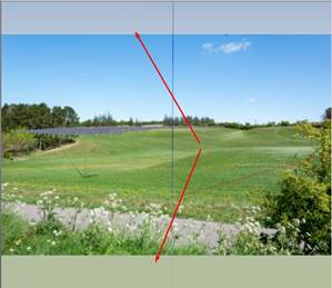
In this case, setting Projection size to “Fit in SketchUp view vertically” would make the image fill out the screen, but then the sides would then be truncated.
Use “Set manually field of view (°)” to set the zoom to an user defined value.
Export format: .jpg format is the most efficient choice. However, it can be worth considering .png if creating a “mask” layer. A mask layer can be used together with the normal PHOTOMONTAGE export, just on the near side of objects to visualize. A .png layer can be edited to be partly transparent. This illustrates the idea:
Use 3D warehouse to bring items into windPRO photomontage
SketchUp has a huge collection of freely available 3D models that can be downloaded and used inside SketchUp as well as in windPRO Photomontage.
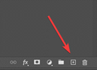
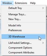
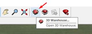
Go into 3D Warehouse using the toolbar or this menu item:
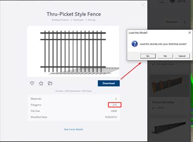
Inside the 3D Warehouse, it is possible to search and filter. It is recommended to set a maximum of polygons to 10 K (10.000), because some models have way too many polygons slowing down the whole process. Here is a search for fences:
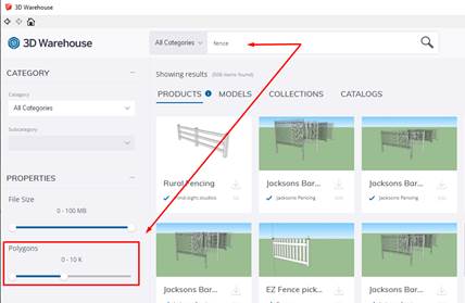
Select a model and download it into SketchUp. Remember that the number of polygons should not be too high.

After downloading, the fence can be moved, rotated, scaled and copied using the basic SketchUp tools:
![]()
If holding Ctrl down while using these tools, the object will be copied. If pressing the arrow keys on the keyboard while using these tools, the action will be locked to a specific axis. Most useful is arrow up (blue axis).
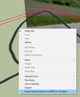
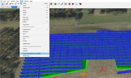
When ready, the relevant items can be selected, and then exported back to windPRO:
The object will then show up as a 3D object in windPRO, and it can be visualized in Photomontage:

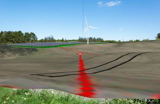
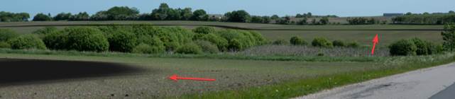
To avoid the shift between the position of the windPRO 3D object and of the resulting 3D structure (in red), the dae file should be placed in SketchUp at the Origin of the coordinate system before export to windPRO.
Postprocessing images in Photoshop
When adding images to SketchUp using the Photomontage creator, and visualizing objects on the photo, it is often necessary to post edit the visualizations in an image editor like for instance Photoshop.
Below some recommendations when using Photoshop, but many other tools can do it in a similarly.
1.
Make sure that “Use maximum
texture size” is selected in SketchUp:

2.
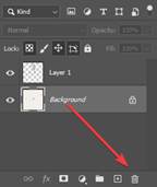
Hide all layers except the
layer with the photo to export the image with no objects as a jpg
file:
3.
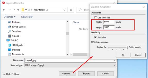
In the Save As dialog, set the
image size to match the size of the original photo:
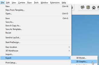
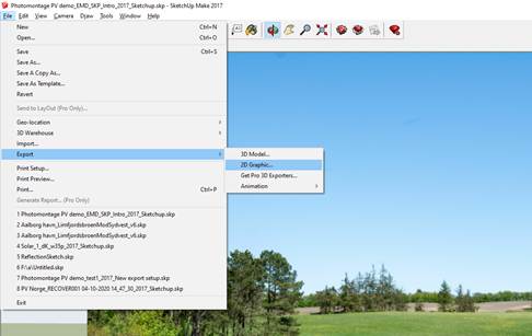
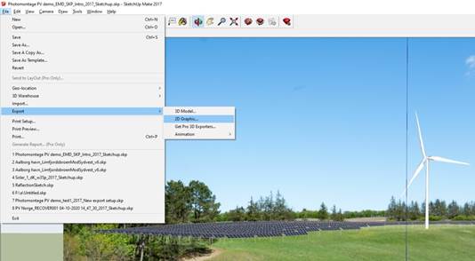
4.
Then export the image with
objects as a 2D graphic jpg file:
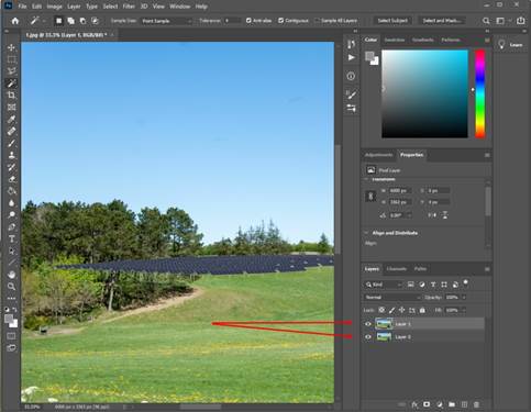
5.
Add the 2 files as layers in
Photoshop, the one with the objects on top:
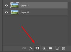
6.
Add a mask to the top layer:
7.
Use the brush tool to paint on
the mask. Paint black to erase, white to un-erase:
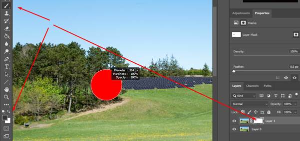
Many other Photoshop tools can be used when painting on the mask, e.g. the magic wand selection tool or paint brushes.
8. Use Save As, to save the result as a jpg file.
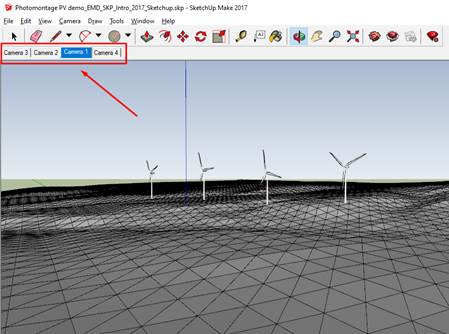
7.2.1.4 Viewpoint Creator
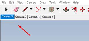
This creator is similar to the PHOTOMONTAGE creator, except that it only creates “scenes” in SketchUp and not the layers and the photos. It can export multiple cameras. This is useful when making visualizations purely artificial and/or to show the model from specific positions. It can also be used to setup viewpoints for a SketchUp animation.
Each exported camera position is exported as a new scene:
The creator setup interface:
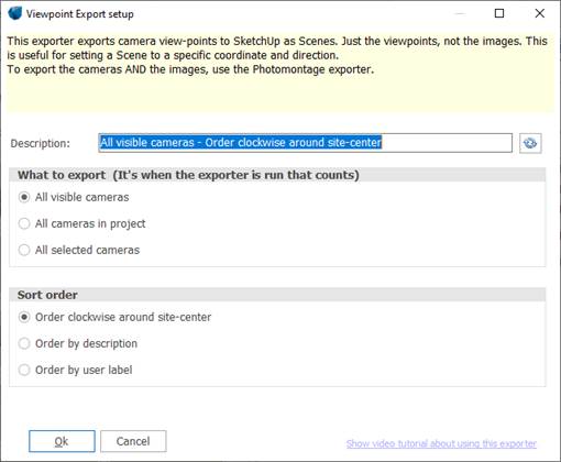
It can be selected what order the scenes (cameras) should have in SketchUp:
· Order clockwise around site-center (default): refers to the direction the camera would move when going from one scene to the next in SketchUp.
· Order by alphabetical order from description name or user label
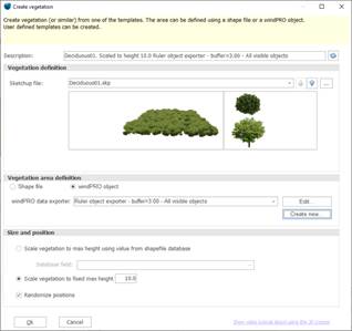
7.2.1.5 Vegetation Creator
This creator can export a collection of 3D objects into a predefined area. This can be trees and bushes, but also many other things. The vegetation can then be re-imported and rendered in a Photomontage.
This is the creator setup:
SketchUp file:
 Select This is the template
containing what to export. windPRO has a predefined set of templates. Also Tthe up down arrows can be
used to change the template:
Select This is the template
containing what to export. windPRO has a predefined set of templates. Also Tthe up down arrows can be
used to change the template: ![]()
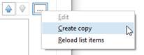
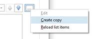
Use the menu to create a user defined template by copying an existing template:
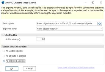
Vegetation area definition is the same setup as for other creators. Here a shape file can be used, or a windPRO object can be used. When using a shape file, the filename must be given. When using a windPRO object, a windPRO to shape file creator must be defined:
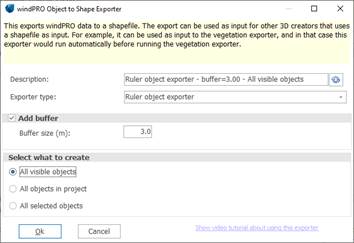
Here is an example of a windPRO to shape creator that uses Ruler objects is shown below. Since the vegetation creator needs a shapefile containing areas and not lines, a buffer must be specified. Using a buffer of 3 meters will create a 6-meter-wide area following the selected rulers:
This shape file is not exported to SketchUp, but just used to define where to export vegetation. To export the shape file itself, then use the Shape file Creator (see 7.3.4.10).
The final setting in the vegetation creator is the Size and position.
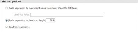
windPRO opens the template and finds the object with the maximum height, and then finds how much it must be scaled to match the setting specified above. Then all objects are scaled with this factor.
If the shapefile used for the export contains a database field containing the height, this field can be used. If a windPRO object creator is used than there would be a Height field when exporting Obstacles or Area objects.
7.2.1.6 Mask Creator
This creates an image mask, which is an Obstacle that has the photo projected on it. It can blend in between other objects that are rendered on the photo. This can be an alternative to using the rubber tool and can be a huge time saver.
An example of usage could be when a line of existing trees on a Photomontage should go in front of some panels and behind others.
Also, it can be used to create more realistic looking 3D models where vegetation and buildings are raised vertically.
When creating several masks at the same time, it gives the highest precision if they are exported from SketchUp to windPRO one at the time! This is because it can be problematic having one huge 3D objects covering a large area. Multiple smaller is better.
Watch the video to learn more!
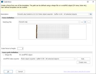
7.2.1.7 Fence Creator
This creator can export a fence following a specified path. The fence can then be re-imported and rendered in a Photomontage.
This is the creator setup:
SketchUp file
Select
the template containing what to export. windPRO has a predefined set of
templates. The up down arrows can be
used to change the template: ![]()
Use the menu to create a user defined template by copying an existing template:
Fence Path definition is the same setup as for other creators. Here a shape file can be used, or a windPRO object can be used. When using a shape file, the filename must be given. When using a windPRO object, a windPRO to shape file creator must be defined:
The example above shows a ruler object exporter
selected as a windPRO object. It will create a line for each selected ruler for
which the selected Fence will be created.
Note that the shape file itself is not exported. To export the shape file itself, then use the Shape Creator (see 7.3.4.10).
The final setting in the Fence Creator is the desired height defined in Scale fence to height.:
![]()
windPRO opens the template and finds the object height and then scale it to above height.
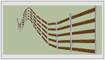
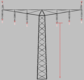
7.2.1.8 Transmission Lines Creator
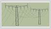
This
creator can export 3D objects ![]() and connect them with wirelines following a
catenary (hyperbolic cosine) curve. The towers and transmission lines can be
re-imported and rendered in a Photomontage.
and connect them with wirelines following a
catenary (hyperbolic cosine) curve. The towers and transmission lines can be
re-imported and rendered in a Photomontage.
The procedure is the following:
1.
Insert 3D objects ![]() where the transmission masts should be. It can
also be substations or similar. Use the same .dae
file for each 3D object if they are the same, that makes it easier. If the
objects are imported from SketchUp they should be imported one at the time!
where the transmission masts should be. It can
also be substations or similar. Use the same .dae
file for each 3D object if they are the same, that makes it easier. If the
objects are imported from SketchUp they should be imported one at the time!
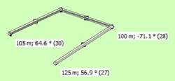
2. Define how many transmission lines should connect the objects, and where they should be attached.
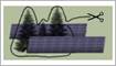
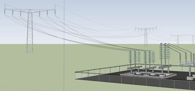
In the example below, some transmission masts and a substation have been created:

When the 3D objects are selected, they can be rotated using the handle. The objects above are rotated as wanted, and now the transmission lines creator can be defined:
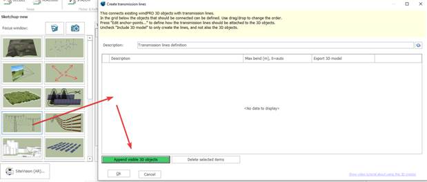
Press the append button to add the visible 3D objects to the list. When they are added to the list, it is shown on the map how they are connected. Here you can see that the substation is added to the leftmost mast, but it should be added to the rightmost.
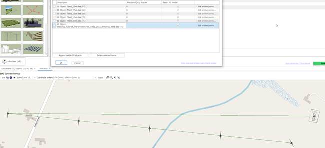
The problem is solved by dragging the substation in the list from the bottom to the top:
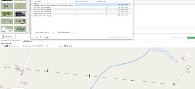
Export 3D model: when checked, both the 3D model and the transmission lines are exported to SketchUp when running the creator. To create only the transmission lines into windPRO, uncheck this box and then check the Re-import to windPRO after export to SketchUp:
![]()
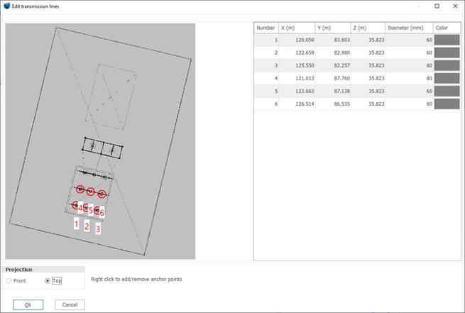
Edit anchor points: from this button, it is possible to define where the transmission lines should be attached to the 3D model:
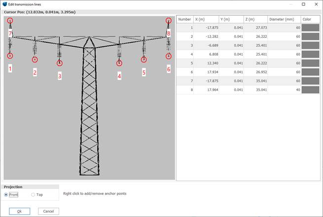
Anchor point 1 is connected to point 1 in the next an previous 3D model, and the same with point 2, 3 etc. If there are more points in one 3D model than in the next, the missing ones is not created.
Mouse Scroll: Zoom in out.
Mouse drag: Move image or drag existing points.
Right-click: Create/Delete anchor points.
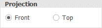
Change the viewing Projection to ensure that the anchor points are placed correctly in all dimensions:
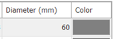
Diameter and color of the lines can be changed here:
An example of substation anchor points seen from top is shown below:
Run the creator and the transmission lines (and optionally the masts and substation) are created in SketchUp. To re-import in windPRO for Photomontage see 7.3.5.
7.2.1.9
Solar PV Creator
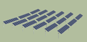
Use this creator to convert a Solar PV area to 3D. This can be useful to manually move/edit the panels before visualizing in Photomontage or to export as 3D models to Google Earth.
Exporter setup interface:
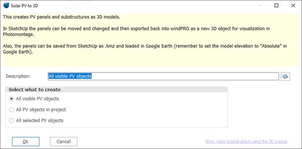
There are three ways to select what PV objects to export
All from visible layers
All in the project
All selected
It is at the time the creator is run it is determined what PV objects to export. It is not when the creator is edited.
After exporting, the PV panels shows up in SketchUp. Besides just visualizing it in the model, it can be modified and exported back to windPRO like this:

This would create a 3D object in windPRO with a copy of the selected items. This 3D object can then be visualized in Photomontage in replacement of the PV panels objects in windPRO. This way this tool can be used to override the layout created by windPRO, but it would not have any effect on the energy calculations!
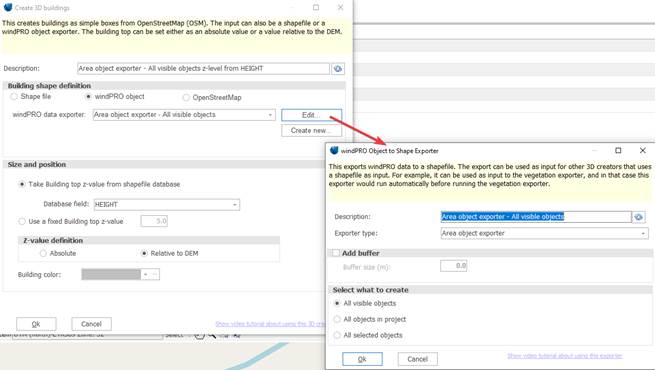
7.2.1.10 Building Creator
This creator allows you to create buildings as boxes from Open Street Map, a shapefile or windPRO objects.
Creator setup:
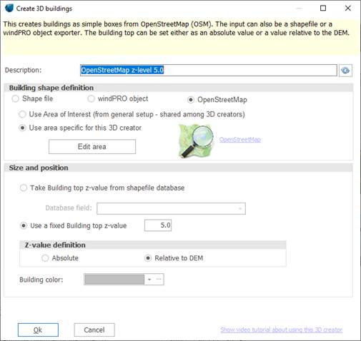
In the example above, OSM is selected as data source.
OSM does not contain the building heights and a fixed building height must be
given with: ![]()
NOTICE: Open Street Map data is not validated by EMD and
is used at own risk and should always be validated manually!
The z-value
definition relates to
the bottom of the building. It can either be available as “Absolute” (Above sea
level) or “Relative to DEM” (Above ground level) as specified from here:
![]()
Finally, the wanted color
can be defined: ![]()
Instead of using OSM or a shapefile, windPRO
object(s) can be used:
In the example above, “All selected Aare objects” is
used, and the field “Height” from the areas is used for getting the building
heights.
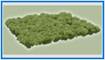
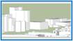
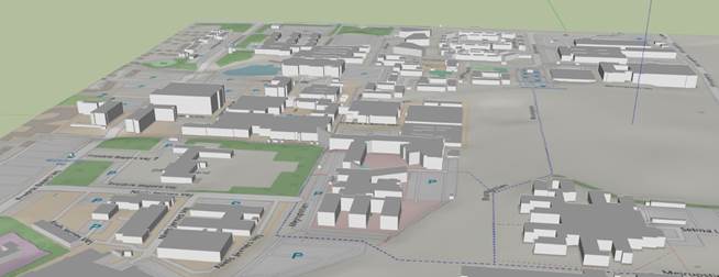
When running the creator, the buildings are created
in SketchUp like this:
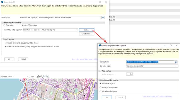
7.2.1.11 Shape Creator
The shapefile creator can export shapefiles, or windPRO objects as shapefiles, to SketchUp.
Here is a setup for exporting the roads for a small city:
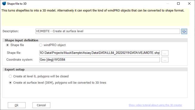
In this case a shapefile containing roads is selected, and the used coordinate system is specified.
Export setup is used to specify where to place the lines vertically. In this example, surface level is selected. windPRO 3.6 does not support 3D shapefiles that contains a z coordinate for each point.
This is how the export looks in a SketchUp project containing a Photomontage export and an Open Street Map surface that is made semi-transparent:
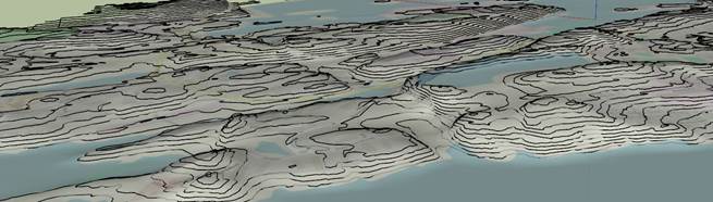
In the example below, the elevation lines object in windPRO has been exported for the same project:
The creator setup:
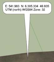
7.2.1.12 Coordinate system setup/exporter
Everything is exported to SketchUp in a cartesian coordinate system where the red axis is pointing at true north at the centre position. The project is automatically geo-located, so shadows are correctly calculated, and it can be correctly exported to Google Earth.
Any other coordinate system can be selected and exported to SketchUp:
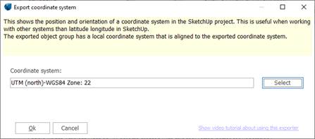
When running the exporter, coordinates system information is shown close to the center of the SketchUp project:
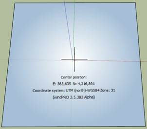
The coordinate system information is shown with a centre point and axis directions. This is enough to establish a connection between any point in SketchUp and this coordinate system. The reason, it is not right at the centre, is simply that it is shown without decimals.
The export is a group, and a group can have a local coordinate system. If using the selection tool and double clicking on the coordinate informer, the group is opened, and then the local coordinate system is activated. The axes are now aligned to the coordinate system. Also, the tape tool is now showing points positions in the local coordinate system, except that the centre offset needs to be added.
SketchUp is not suitable for creating very large GIS projects covering many kilometres, because of Earth’s curvature!
7.2.1.13 Result layer Creator
This creator can export a result layer as a
3D volume to SketchUp
Export a
result layer as a 3D volume to SketchUp
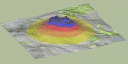
The result layer creator shares many options with the background map creator. It exports a result layer as a 3D volume, where the data in the result layer is scaled to a height:
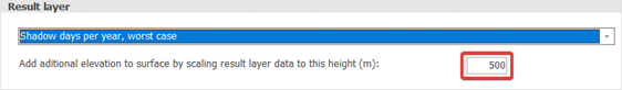
In above case the lowest result layer value is given the height 0m and the highest is given the height 500m and the rest is scaled linearly. This height is added to the surface height. The surface can be the DEM or a flat surface. See the background map creator description for details.
Here is an example where a Noise Calculation result layer is exported with the values 0, 500 and 1000:
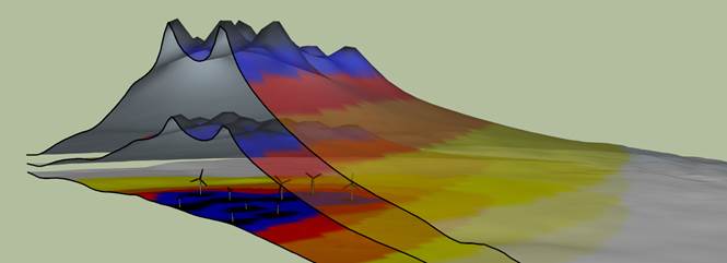
A “Section Plane” is also applied:
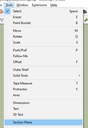
7.2.1.14 DWG/DXF Exporter
From applications like Revit or AutoCAD, 3D models can be exported to DWG, and sometimes this is done using a specific coordinate system. If such a DWG file is imported normally in SketchUp it must be positioned manually in the model, but if thanks to the DWG/DXF Exporter, the model is placed correctly in the SketchUp project.
You simply select the .dwg file, specify the coordinate system, and the import options:
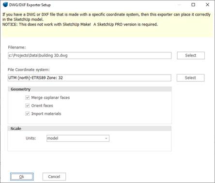
Apart from the filename and the coordinate system, the other parameters are a copy of the import options from SketchUp and the meaning can be found in the SketchUp manual:
https://help.sketchup.com/en/sketchup/importing-and-exporting-cad-files#import-cad
7.2.1.15 CFD creator
This creator can export .cfdresult and .flowres files as 3D quiver plots.
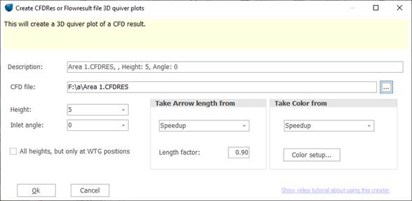
CFD file: can be either a .cfdres or a .flowres file
Height: the available height values are read from the file. Only a single height can be exported at the time, except if just exporting at WTG positions.
Inlet angle: the available inlet angles are read from the file.
All heights, but only at WTG positions: all heights are shown for each WTG position. Values are interpolated to get the exact position.
Take arrow length from: the length of the arrows in the quiver plot is taken from this value. Available values are read from the file.
Length factor: the arrow length is scaled by this value. If the value is 1 then the longest arrow in the export, has the length of a data cell. Sometimes the dataset can contain a few extreme values, and all other arrows will be very short. In this case it makes sense to use a higher scaling value.
Take color from: to define where the arrow color should come from. It can be the same as the length, or it can be different.
The export can be viewed in Google Earth as well. See the video tutorial for more information: Video tutorial
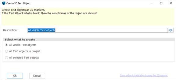
7.2.1.16 Text object Creator

The text object creator can export a text object to SketchUp. It can be useful for showing geographical information or highlight specific coordinates. If exporting a text object with no text, then the coordinate is shown instead, in the currently selected coordinate system:
This is the creator setup:
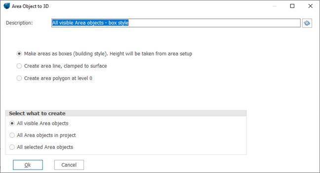
7.2.1.17 Area Object Creator
This creator is a combination of the building creator and the shape object creator, just only working with area objects. It is made for making it easier/more understandable for users who is used to the area object.
7.2.1.18 3D object creator
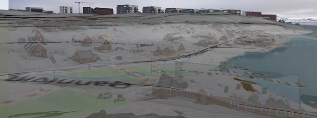
The 3D object creator can export 3D objects to SketchUp at the positions they are in windPRO, but more importantly they can be exported with textures from a photomontage. This is very useful, because it means that any object created in SketchUp can be exported to windPRO and then exported back with a texture from a Photomontage image. See the video tutorial for more details.
This is the creator setup:
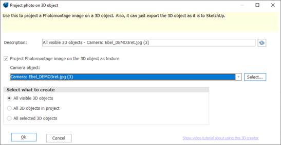
Project Photomontage image on the 3D object as texture: with this option, the objects texture is replaced with a projection of a Photomontage image.
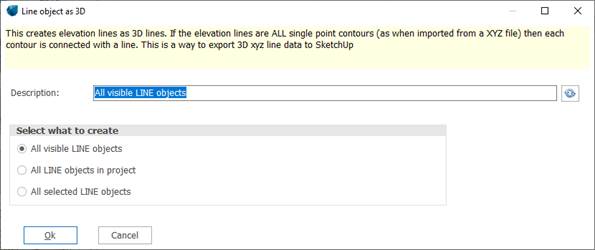
7.2.1.19 Line Object Creator
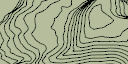
The line object creator can export elevation ISO lines object to SketchUp. Currently it is not possible to export other line object properties.
The same thing can be done from the Shape Creator.
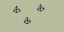
7.2.1.20 Obstacle Object Creator
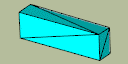
The object creator can export Obstacles SketchUp at the positions they are in windPRO.
This is the creator setup:
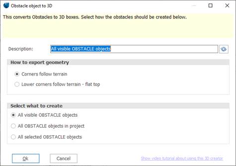
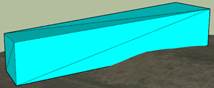
Corners follow terrain: the lower corners follow the terrain and the top corners are all offset the height of the obstacle from the lower corners.
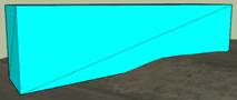
Lower corners follow terrain – flat top: the lower corners follow the terrain and the top corners are set to the highest value of the lower corners plus the obstacle heights.
7.3 From SketchUp to windPRO
Any
object in SketchUp can be exported to windPRO, as long as
they are correctly defined in the coordinate system. Therefore, it is an
advantage to create the SketchUp project from windPRO, with a surface export
for example. Objects exported from SketchUp are imported in windPRO in a 3D
object ![]() .
.
There are 2 options to export from SketchUp to windPRO:
1) with the automatic Re-import to windPRO after export to SketchUp , selected from the main window. This option can be used when no manual adjustment needs to be made in SketchUp. It is especially relevant for Vegetation, fences, and transmission lines.
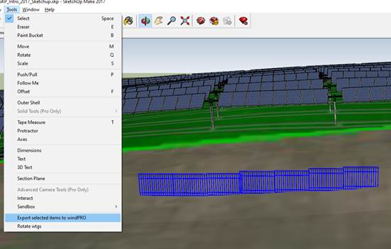
2) from SketchUp, after selecting the object, go to Tools and click on Export items to windPRO
7.3.1.1 Use the 3D warehouse to bring items into windPRO photomontage
SketchUp has a huge collection of freely available 3D models that can be downloaded and used inside SketchUp as well as in windPRO Photomontage.
Go into 3D Warehouse using this button in the toolbar:
Inside the 3D Warehouse, it is possible to search and filter. It is recommended to set a maximum of polygons to 10 K (10.000), because some models have way too many polygons slowing down the whole process. Here is a search for fences:

Select a model and download it into SketchUp. Remember that the number of polygons should not be too high.
After downloading, the fence can be moved, rotated, scaled and copied using the basic SketchUp tools:
![]()
If holding Ctrl down while using these tools, the object will be copied. If pressing the arrow keys on the keyboard while using these tools, the action will be locked to a specific axis. Most useful is arrow up (blue axis).
When ready, the relevant items can be selected, and then exported back to windPRO:
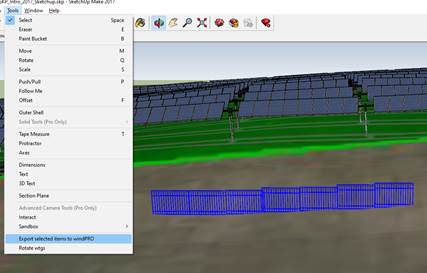
The object will then show up as a 3D object in windPRO, and it can be visualized in Photomontage:
To avoid the shift between the position of the windPRO 3D object and of the resulting 3D structure (in red), the dae file should be placed in SketchUp at the Origin of the coordinate system before export to windPRO.
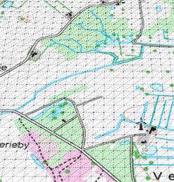
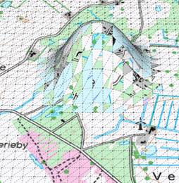
7.3.1.2 Create/edit elevation data and import in windPRO
See the YouTube video about using this feature: Link to YouTube

This feature can create elevation data in windPRO based on the data from SketchUp.
Above animation is using the SketchUp Sandbox tools that is part of the standard SketchUp installation, also in the free SketchUp Make 2017. More sophisticated commercial plugins to SketchUp exists. See links at the end of this section.
When items are exported from SketchUp to windPRO it is normally as 3D objects, but since the content is containing a set of triangles, these can just as easily be used as TIN in an elevation object.
To export a set of selected lines (triangles) to windPRO follow these steps:
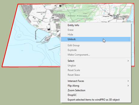
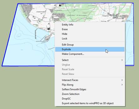
1.
If using elevation surface from
windPRO then first unlock and explode the surface
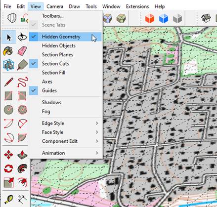
2.
Enable
View Hidden Geometry
3. Make the desired modifications (see links below for help)
 =>
=> 
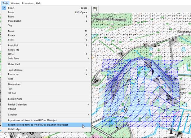
4.
Select
the triangels to use for elevation data in windPRO, and select this menu item:
Now this dialog shows up in windPRO:
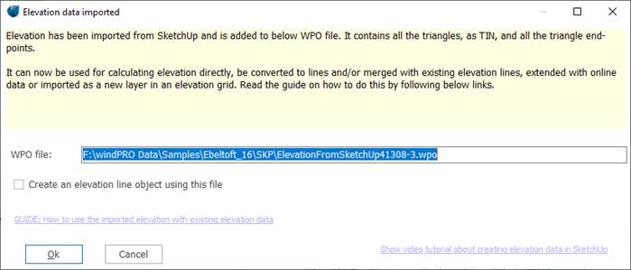
The .wpo file created can be loaded into a
line object as elevation lines, but it really only
contains points (trinangle endpoints), and a complete
TIN. This can work fine as a default TIN elevation object, but if the object is
put into edit-mode, the TIN is dismissed, and after edit a new, and different,
TIN is created. To merge the TIN into other existing data, it can be imported
as a new layer in an elevation object, or it can be merged with an existing
line object. To merge with an existing line object, the new object should first
be converted to real lines in the EMD editor using “Change contour interval”,
and then extended with the line object it should be merged with, still in the
EMD Editor, with “Extend data”.
There are many resources around on how to work with terrain data in SketchUp. Here are a few links:
Sandbox tools
How a Landscape Architect
Grades a Site
Top 5 Extensions for
Landscape Site Analysis
https://artisan4sketchup.com/sculpt/
7.4 Sketchup tips
7.4.1.1 Sketchup viewer
Trimble has developed (free) viewers for many different platforms that makes it possible to view a SketchUp project, and as a result also a windPRO project, on a PC, Mac, mobile phone or VR glasses (not free).
The different viewers can be downloaded from here:
https://www.sketchup.com/products/sketchup-viewer/downloads
For Android: https://play.google.com/store/apps/details?id=com.trimble.buildings.sketchup
For iPhone: https://itunes.apple.com/us/app/sketchup-mobile-viewer/id796352563?ls=1&mt=8
With the AR feature of the SketchUp app the model can be placed on a floor,a table (or any smooth and horizontal surface), and it is possible to walk around/inside the project:
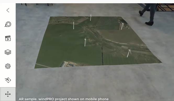
Here is a demo video made from a screen
capture on an Android phone: Video
Note that the AR feature is not free but costs $9.99 USD/yr (June 2021).
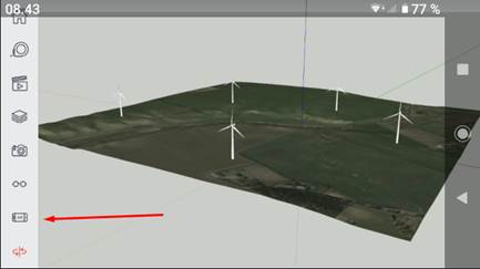
When the project is loaded, the AR feature can be started from this button:
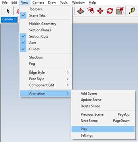
7.4.1.2 Creating animation in SketchUp
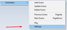
SketchUp can export animations to video. First the animation can be set up and played from this submenu:
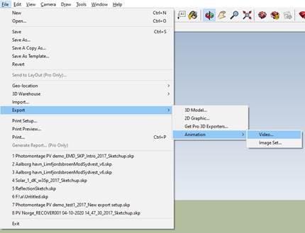
And then the export itself can be initiated from here:
The main principle in an animation, is that SketchUp moves the camera from scene to scene:
Based on the settings in the animation submenu, and the scene setup:
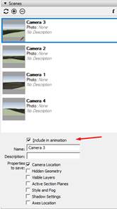
This means that the project needs to include scenes to create an animation. To do more advanced animations, not based on scenes, this plugin offers many possibilities: https://sketchucation.com/plugin/1839-animator
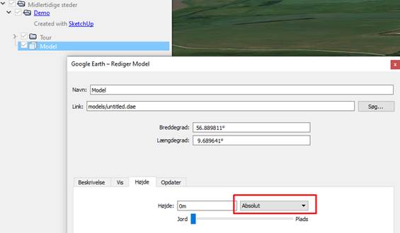
7.4.1.3 Exporting to Google Earth
The visible items can be exported to Google Earth. Select Export 3D Model:
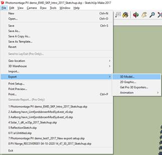
Select .kmz format
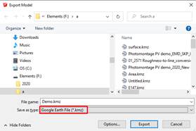
After opening in Google Earth right click on model, go to Properties, and change model height from Relative to Absolute:
7.4.1.4 SiteVision
SiteVision is an outdoor augmented reality system that allows to visualize 3D data live in the environment from a smart phone or a tablet. SiteVision has been developed by Trimble (https://sitevision.trimble.com).
SiteVision button can be used to convert the active SketchUp project to a format that SiteVision can understand. It means that the SketchUp project is converted to UTM WGS84 and its current zone. A file is also created with the same name as the SketchUp project, but with a .jxl extension. This file contains information about the used coordinate system, and if this file is present together with the SketchUp file, then SiteVision can read it and place the model correctly.
To transfer the SketchUp project to the SiteVision app:
1.
Use the button to create a
SiteVision ready version of the SketchUp project:
![]()
2.
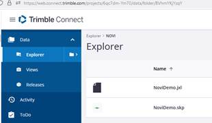
Copy the project to Trimble Connect. Drag drop the files to the wanted folder:
3.
Open SiteVision on the mobile
phone or tablet and select Load model:
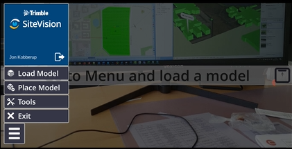
4.
Select Trimble Connect:

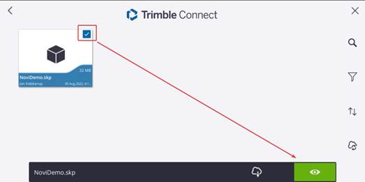
5.
Tick the model and tap the eye
button:
This should open the project on SiteVision, and it should now be positioned correctly.